


LTS Series Driver is a high-performance LED driver that provides smooth, continuous <5% dimming for virtually any LED fixture, It provides constant current CCR dimming mode. It can work in either the phase cut dimming mode or the 0-10V dimming mode, providing integrated products from multiple dimming products.
The LED current is allowed to be set and is programmed by the GUI port.
It is the most versatile LED driver offered today due to its compatibility with a wide
variety of LED arrays, multiple form factors, and numerous control options.
|
Key Features |
|
|
■ Drive Mode: |
Constant current, phase cut dimming, 0-10V dimming. |
|
■ Technology: |
Active PFC 2-Stage Switch Mode. |
|
■ Input Voltage: |
120 to 277 Vac. |
|
■ Output Power: |
21Watt Max. |
|
■ Dimming: |
Smooth & Continuous Dimming from 5% to 100% with 0-10V. dim to off. |
|
LEDs turn on to any dimmed level without going to full brightness. |
|
|
Constant Current Reduction (CCR) dimming methods. |
|
|
0-10V (Class 2): |
Secondary side DC Dimming. Work in the AC 120-277V range. |
|
AC Phase Cut: |
Primary side AC phase cut dimming, Work in the AC 120V. |
|
■ Programming: |
The maximum output of 0-10V and Phase cut can be set by GUI. |
|
■ Output: |
26 to 42 Vdc/ 100 to 300 mA and 250 to 500 mA (Set by GUI). |
|
■ Efficiency: |
Up to 83%. |
|
■ Warranty: |
5 years. |
Special Features
■ Continuous dimming from 5% to 100% with 0-10V. dim to off.
■ This product has both 0-10V dimming and phase cut dimming, but only
single dimming.
■ 0-10V dimming control is isolated for AC input and DC output.
■ The programmable function is effective for 0-10V dimming and phase cut dimming.
■ Safety isolation between primary and secondary.
■ A rated lifetime of 50,000 hours @ Tc = 80°C.
■ Safety: UL8750, Class P, Class 2, CSA22.2.
■ EMC: FCC 47 Part 15: Class B @120V & Class A @277V.
■ Surge Immunity Test: AC Power Line: line to line 2 kV.
■ Ring wave: NEMA SSL1-2010Non-Roadway, 100KHz ring wave, 2.5KV, common and differential mode.
■ Metal case, Used with silicone potting. Meet the RoHS directive.
■ IP20, suitable for Dry & Damp.
YG Programmer PC Based Software, USB Interface
Programmable Output Current (POC): Programmable Iout from 100mA to 500mA.
Programming Tool:
The YG Programmer is a programming and configuration tool for YG intelligent programmable LED drivers. It consists of the YG programmer which is connected between the USB port of a computer and the LED driver being programmed, and the YG programmer software. The YG programmer software is a PC based graphical user interface that allows the user to program and configure the operating parameters of an YG Programmable LED Driver. This interface allows the operator to set the LED drivers output current within its specified range.
YG Programmer:
Is the physical USB unit connected between the USB port of a computer and the LED driver being programmed? This unit also provides all power required to the LED driver being programmed. No connection to an AC power source is required for programming the LED driver.
YG Programmer Software:
The YG Programmer software is the windows based GUI that allows the user to assign custom part number(s) to the LED driver being programmed. The user can then save the profile to a computer disk and recall as need. The user can then use the "Auto Program" feature to quickly program as many LED drivers with the saved profile as is required. Each driver programming simply requires a click of the mouse to program in a single step.
The YG Programmer software supports bar code scanners. The barcode scanner can be used to automate the programming of the attached LED driver. The barcodes scanner interface also provides an option to either enable or disable logging of the parameters to an excel file.
PC programming mode is through the programmer PRG-01A two wires connected to the driver, by the GUI interface automatically complete the operation, there are engineering mode and factory mode. This mode requires the programmed driver to power on.
NFC programming mode is through the programmer PRG-02A (hand-held) or PRG-02B (seat), automatically completed by the GUI interface, there are engineering mode and factory mode. This mode requires the antenna window of the driver to be near the programmer.
20W&12W Dual Dim Constant Current Reduction (CCR) Part List
|
Part Number |
Dimming mode |
Input Voltage (Vac) |
Output Voltage Range (Vdc) |
Maximum output current set by GUI |
Output current range of dimming |
Current Accuracy |
Power Factor |
Output Power max |
Efficiency max |
|
LTS20W-42-C0500-E-F-S LTS20W-42-C0500-E-J-S |
0-10V |
120 |
26 - 42 |
250-500 mA Default setting: 500mA |
5-100% |
±5% |
0.9 |
21 W |
83% |
|
0-10V |
277 |
5-100% |
±5% |
||||||
|
Phase Cut |
120 |
5-100% |
±7% |
||||||
|
LTS12W-42-C0300-E-F-S LTS12W-42-C0300-E-J-S |
0-10V |
120 |
26 - 42 |
100-300 mA Default setting: 300mA |
5-100% |
±5% |
0.9 |
12.6 W |
80% |
|
0-10V |
277 |
5-100% |
±5% |
||||||
|
Phase Cut |
120 |
5-100% |
±7% |
Note:
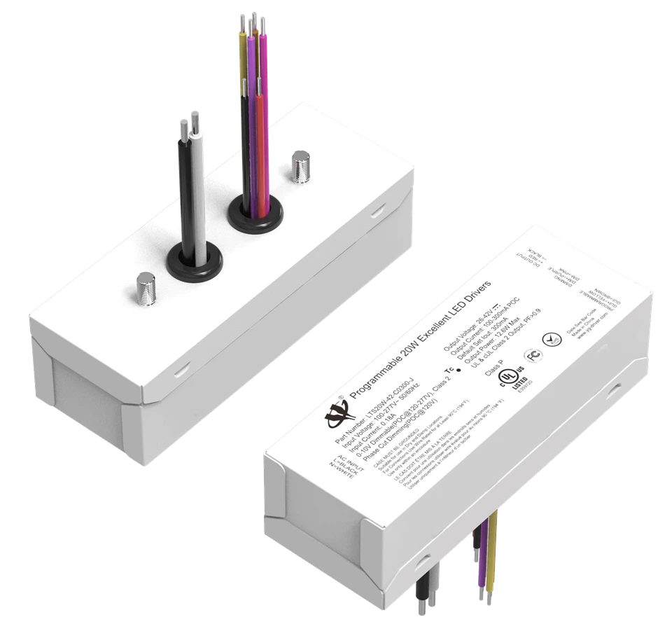
*-E is E version, -F is the side outlet shell, -J is the top outlet housing, -S stands for stripe-free shell.
Input Specifications
|
Parameter |
Min. |
Typ. |
Max. |
Notes / Conditions |
|
Rated Input Voltage |
120 Vac |
--- |
277 Vac |
120, 277 Vac Nominal Values. |
|
Input Frequency |
47 Hz |
50/60 Hz |
63 Hz |
|
|
Input AC Current |
--- |
--- |
0.3 A |
Measured at 120 Vac / 60Hz Input, Output Full Load. |
|
--- |
--- |
0.09 A |
Measured at 277 Vac / 60Hz Input, Output Full Load. |
|
|
Inrush Current ( Peak ) |
--- |
5 A / 28uS |
9 A / 36uS |
Measured at 120 Vac / 60Hz Input, Output Full Load. |
|
--- |
7 A / 32uS |
12 A / 40uS |
Measured at 277 Vac / 60Hz Input, Output Full Load. |
|
|
Leakage Current |
--- |
--- |
300 μA |
Measured at 120 Vac / 60Hz Input, Output Full Load. |
|
--- |
--- |
700 μA |
Measured at 277 Vac / 60Hz Input, Output Full Load. |
|
|
THD |
--- |
--- |
20% |
Measured at 120, 277 Vac Input, ≥ 50% Load. Only suitable for CC & 0-10V dimming mode. |
|
Power Factor ( PF ) |
0.9 |
--- |
--- |
Output Specifications
|
Parameter |
Min. |
Typ. |
Max. |
Notes / Conditions |
|
DC Output Voltage |
26V |
--- |
42V |
Measured at 120, 277 Vac Input. |
|
Output Power |
--- |
--- |
21W |
Measured at 120, 277 Vac Input. LTS20W. |
|
--- |
--- |
12.6W |
Measured at 120, 277 Vac Input. LTS12W. |
|
|
Flickering Index ( Ipk-pk ) |
--- |
+5% |
+10% |
20MHz BW, Full load output in parallel with 0.1uF & 10uF CAP. Flickering Index is defined as [(Imax-Imin)/(Imax+Imin)] * 100%. |
|
Line Regulation |
-5% |
--- |
+5% |
Maximum over entire range of input voltage / output loads (any combination), and temperature range. |
|
Load Regulation |
-5% |
--- |
+5% |
|
|
Start-up Delay |
--- |
--- |
500ms |
From VAC turn-on until output current reaches 90% of nominal value. Output Full Load. |
|
Turn-off Delay |
--- |
--- |
500ms |
LED's not lit, No die glow. |
|
Output Overshoot |
-5% |
--- |
+10% |
Measured at 120, 277 Vac Input, When power on or off. |
Protection Specifications
|
Parameter |
Min. |
Typ. |
Max. |
Notes / Conditions |
|
Output Over Voltage ( OVP ) |
--- |
--- |
55V |
No Damage. Auto recovery when the leads are open. |
|
Output Short Circuit ( SCP ) |
--- |
--- |
--- |
No Damage. Auto recovery after short is removed. |
|
Over Temperature Protection (OTP) |
90℃ |
100℃ |
110℃ |
The temperature is 100±10℃. |
Dimming Specifications
|
Items |
Parameter |
Min. |
Typ. |
Max. |
Notes / Conditions |
|
0-10V Dimming |
Turn-on Time |
--- |
--- |
500 ms |
This time is AC input to the DC 90% output current. Full load. |
|
Flicker |
--- |
+5% |
+10% |
Current ripple is defined as [(Imax-Imin)/(Imax+Imin)] * 100%. |
|
|
Shimmer |
--- |
2% |
5% |
Long Term Current Stability (Average can't vary by more than X% over 10s period). |
|
|
Dimming Curve Type |
Similar to Linear |
||||
|
Dimming Level Voltage |
1.0 V |
--- |
8.3 V |
Minimum Light Output, Maximum Light Output. |
|
|
Input Absolute Voltage |
0 V |
10 V |
12 V |
Purple Wire. |
|
|
Output Source Current |
100 uA |
--- |
500 uA |
Purple Wire. |
|
|
Dimming CCR Output Current |
5% |
--- |
100% |
CCR output. |
|
|
Output Current in 0-10V Pin Open |
--- |
Normal |
--- |
It's a constant current output with active PFC. |
|
|
Output Current in 0-10V Pin Short |
--- |
Min. |
--- |
CCR output. |
|
|
Phase cut Dimming |
Turn-on Time |
--- |
--- |
500 ms |
At about 100% dim level. This time is AC input to the DC 90% output current. |
|
Flicker |
--- |
+5% |
+10% |
Current ripple is defined as [(Imax-Imin)/(Imax+Imin)] * 100%. |
|
|
Dimming CCR Output Current |
5% |
--- |
100% |
CCR output. |
|
|
Shimmer |
--- |
--- |
7% |
Long Term Current Stability (Average can't vary by more than X% over 10s period). |
|
|
Dimming Curve Type |
Similar to Log |
||||
|
Acoustic Noise |
--- |
22 dBA |
24 dBA |
Class A , on one meter away. |
|
General Specifications
|
Parameter |
Min. |
Typ. |
Max. |
Notes / Conditions |
|
Cooling |
Convection |
|||
|
Life Time |
50,000 hours |
Measured at 120 Vac input, 100% Load and Tc=80° C |
||
Environmental Specifications
|
Parameter |
Min. |
Typ. |
Max. |
Notes / Conditions |
|
Case Temperature ( Tc ) |
--- |
--- |
+90 °C |
Measured at location specified on case. |
|
Operating Temperature ( Ta ) |
-30 °C |
--- |
+55 °C |
This is a reference range. Tc controls temperature range. |
|
Storage Temperature ( Ts ) |
-40 °C |
+85 °C |
Non operating temperature range. |
|
|
Operating Humidity |
--- |
--- |
95% RH |
Relative Humidity. Non condensation. |
|
Vibration |
5 Hz |
--- |
55 Hz |
1G, 10 minutes / 1 cycle, period 30 minutes, each along X, Y, Z axis. |
Safety Compliance
|
Safety Category |
Standards / Notes |
|
UL / cUL |
UL8750, CSA22.2, Class 2, UL Class P. |
|
Withstand Voltage |
Input to Output 2000 Vac; Input to Dim: 1600 Vac; Input to FG: 1600 Vac; Output to Dim: 500Vac; Output to FG: 500Vac; Input to GUI/NTC 1600 Vac; GUI/NTC to FG: 500 Vac. |
|
Isolation Resistance |
Input to Output: >10MΩ, 500Vdc @ 25°C, 70% RH. |
|
Dimming |
DIM+, DIM- are insulated from secondary circuits. |
|
FG |
The metal case of the driver must be connected to earth ground (FG) in the end-use application |
EMC Compliance
|
EMI Category |
Standards |
|
FCC |
FCC 47 Part 15: Class B @120V & Class A @277V. |
|
Ring wave |
NEMA SSL1-2010Non-Roadway, 100KHz ring wave, 2.5KV, common and differential mode. |
Note: the above test data are in the condition of 25℃ ambient temperature, except for the marked temperature.
Typical Applications
LED Forward voltage: VF = 3.0V~3.5V
■. Driver Phase Cut CCR Dimming
|
AC Input |

|
LTSxxW-42-C0xx0-E-J/F-S Phase Cut Dimming |
|
+ = Red |
|
- = Black |
|
DC Output |
|
N = White |
|
L = Black |
|
GUI + - |
|
( ) |
|
FG=(Case) |
■. About Phase cut dimmer
|
ELV dimmer |
► Electronic Low Voltage dimmer. ► Trailing Edge phase dimmer. ► Reverse phase control dimming. |
 Reverse phase Reverse phase
be cut |
► high stability. ► low noise. ► highest cost. |
|
|
TRIAC dimmer |
► Incandescent phase dimmer. ► Leading Edge phase dimmer. ► SCR phase dimmer. ► Forward phase control dimming. |
|
► little worse stable. ► a little noise. ► lowest cost. |
 Forward phase
■. Driver 0-10V CCR Dimming
|
AC Input |

![]()
![]()
|
LTSxxW-42-C0xx0-E-J/F-S 0-10V Dimming |
|
(PURPLE) |
|
IP710 Wall Dimmer |
|
(PINK) |
|
PWM Pulse or Dimmer |
|
|
|
or |
|
Zigbee |
|
or |
|
DC+12V |
|
or |
|
DALI or DMX |
|
DC+12V |
|
or |
|
V |
|
0-10V SINK |
|
I/O |
|
GND |
|
Dim |
|
+ = Red |
|
- = Black |
|
DC Output |
|
N = White |
|
L = Black |
|
GUI + - |
|
( ) |
|
FG=(Case) |
 Dimming Curve
Note:
1. The maximum deviation of the 0-10V dimming curve parameters above is ± 0.5.
2. Vdim (max):8.30±0.30 (7.9-8.6V); Vdim (on):1.05±0.15 (0.9-1.2V); Vdim (off):0.5±0.15 (0.35-.65V).
3. The above test data are in the condition of 25℃ ambient temperature.

GUI Page


Note:
◆ Custom designs available.
◆ Please consult with the factory.
◆ Specifications subject to change
without notice.
Power Operating Window

|
Minimum POC |
|
DLC working area |
|
|

|
Minimum POC |
|
DLC working area |
PF>0.9 and THD<20%, Window that meet DLC standards at input 120-277V range.
Power Operating Window.
Note: When the output current is set, the output voltage is automatically limited within the curves.
 Characteristic Curve


Installation
Metal shell. This product has two 4mm mounting holes.
AC input for connection the two core ANSI/UL1015/AWG18 temperature 105 °C core copper wire connection.
Cable Length: 155mm, stripping on the tin: 10mm.
Where: L - Black wire, N - White wire.
DC output for connection the two core ANSI/UL1569/AWG18 temperature 105 °C core copper wire.
Cable Length: 155mm, stripping on the tin: 10mm.
Where: DC+ - Red, DC- - Black.
The dimmer control input is the three copper wires, ANSI/UL1569/AWG22 & temperature 105 °C.
Cable Length: 175mm, stripping on the tin: 10mm.
Where: Dim+ (0-10V) input - Purple wire, Dim- (0-10V) - Pink wire.
GUI programmable, ANSI/UL1569/AWG22 & temperature 105 °C.
Cable Length: 175mm, stripping on the tin: 10mm.
Where: GUI+ - Yellow wire, GUI- - Brown wire.
Order ID
P/N: LTS20W-42-C0500-E-J/F-S
Description: 20W, 42Vdc voltage max, constant current 250-500mA (Set by GUI),0-10V & phase cut CCR dimming mode.
P/N: LTS12W-42-C0300-E-J/F-S
Description: 12.6W, 42Vdc voltage max, constant current 100-300mA (Set by GUI),0-10V & phase cut CCR dimming mode.
Product Size
 P/N: LTS**W-**-C****-E-F-S
P/N: LTS**W-**-C****-E-J-S

Programming Connection Diagram
|
PC Programming: PC+ (red) → Driver GUI+ (yellow) PC− (black) → Driver GUI- (brown) |


|
|


Note:
■ The independent LED drive conforms to the EMC standard. But it is not guaranteed to be qualified when the drive is mounted in the LED Fixture.
■ Please forgive us for any discrepancy due to the update of the specifications or the upgrade of the product. If you need the latest information, please contact our marketing department.
Hot Tags: lts series dual dim, pc programmable, led driver, us & cn class 2, China, suppliers, manufacturers, factory, price, made in China


