Ⅰ. Product Overview
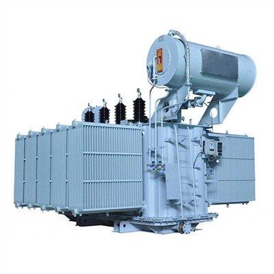
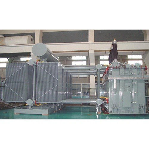
110kV power transformers integrate advanced core optimization technologies, utilizing grain-oriented silicon steel cores coated with curing paint for reduced losses (≤84.8kW) and noise levels. Available in two configurations:
Three-Phase Two-Winding Type (Capacity: 6.3–120 MVA)
Three-Phase Three-Winding Type (Capacity: 6.3–100 MVA)
Both support OLTC (On-Load Tap Changer) or NLTC (No-Load Tap Changer) voltage regulation.
|
110kV 3-phase 2-winding Power Transformer |
|
|
Product Attributes |
|
|
Model No. |
|
|
Application |
Power |
|
Coil |
Core-type Transformer |
|
Frequency |
50/60Hz |
|
Phase |
Three |
|
Cooling Method |
Oil-immersed Type Transformer |
|
Capacity range: |
6300kVA-100000kVA |
|
Operating Ambient Temperature |
+40 °C--30 °C |
|
Operating Altitude |
≤1000m |
|
Operating Max Wind Speed |
≤35m/s |
|
Earthquake acceleration |
horizontal acceleration ≤0.3g |
|
vertica I acceleration ≤0.15g |
|
|
Standard |
IEC 60076-1:2000, IEC 60076-2:1993, IEC 60076-3:2000, IEC 60076-5:2006, IEC 60137:2003; ANSI, IEEE, AS, etc. |
|
Supply Ability & Additional Information |
|
|
Packaging |
Seaworthy Packing |
|
Transportation |
Ocean |
|
Supply Ability |
High |
|
HS Code |
85042100 |
|
Payment Type |
L/C, T/T |
|
Delivery Time |
60 Days |
|
Place of Origin |
China |
|
Port |
China Sea Port |
|
Incoterm |
FOB, CFR, CIF |
|
Packaging & Delivery |
|
|
Selling Units: |
Set/Sets |
|
Package Type: |
Seaworthy Packing |
Ⅱ. Key Features & Innovations
Ultra-Low Loss Design
Transposition optimization reduces circulating current loss by 35% vs. GB/T 6451-2008 standards.
Core slotting minimizes structural heat generation.
Short-Circuit Resilience
Hydraulic transposition tools + hot-set assembly ensure 220kV-grade structural strength.
Noise Suppression
"Soft connection" between core and tank cuts noise transmission.
Partial Discharge Control
Electric field analysis extends service life by preventing concentrated discharges.
Seismic Resistance
Withstands horizontal acceleration ≤0.5g (exceeding industry norms).

2. High Resistance to Short Circuit
① Hydraulic transposition tools are used for conductor transposition.
② The body adopts constant pressure drying and overall assembly, and the overall assembly adopts hot set.

3. Low Noise
The iron core is "soft connected" with the oil tank as a whole to reduce the transmission of noise from the body to the oil tank.
4. Low Temperature Rise
Control of transverse eddy current losses in windings.
5. Low partial discharge, extend Transformer Service life.
Analytical calculation of the electric field and improvement of the area where the electric field is concentrated.

6. Potential distribution is effectively improved by application of software to calulate the impact potential distribution and gradient potential distribution, calculate the potential distribution between the various parts of the coil, between the coil and the coil, coil and earthing.

7. High Earthquake Resistance
The casing design uses the dynamic design method, the horizontal acceleration is taken as 0.5g, the waveform is taken as resonant sinusoidal third harmonic, and the loading part is the lower end of the casing flange seat. The transformer body adopts the static design method, and the static horizontal acceleration is 0.5g.
8. Transformers Have Good Mechanical Strength
Eliminate the weak point of structural member strength and improve the mechanical strength of structural members through software simulation calculation.
Part Ⅲ: Product Main Parameter
|
6300~120000/110 Two-winding Oil-immersed Transformer with NVTC |
||||||||
|
Rated Capacity (kVA) |
Rated Voltage and Tapping Range |
Vector Group |
Impedance Voltage % |
No Load Current |
No Load Losses |
On Load Losses |
||
|
HV |
Tapping Range % |
LV |
||||||
|
6300 |
110, 121 |
±2×2.5% |
6.3, 6.6, 10.5, 11 |
YNd11 |
10.5 |
0.77 |
9.3 |
36 |
|
8000 |
0.77 |
11.2 |
45 |
|||||
|
10000 |
0.72 |
13.2 |
53 |
|||||
|
12500 |
0.72 |
15.6 |
63 |
|||||
|
16000 |
0.67 |
18.8 |
77 |
|||||
|
20000 |
0.67 |
22 |
93 |
|||||
|
25000 |
0.62 |
26 |
110 |
|||||
|
31500 |
0.6 |
30.8 |
133 |
|||||
|
40000 |
0.56 |
36.8 |
156 |
|||||
|
50000 |
0.52 |
44 |
194 |
|||||
|
63000 |
0.48 |
52 |
234 |
|||||
|
75000 |
12~14 |
0.42 |
59 |
278 |
||||
|
90000 |
0.38 |
68 |
320 |
|||||
|
120000 |
0.34 |
84.8 |
397 |
|||||
|
6300~100000/110 Three-Winding Oil-immersed Transformer with NVTC |
|||||||||
|
Rated Capacity (kVA) |
Rated Voltage and Tapping Range |
Vector Group |
No Load Current |
Impedance Voltage % |
No Load Losses |
On Load Losses |
|||
|
HV |
MV |
LV |
Step up |
Step down |
|||||
|
6300 |
110±2×2.5%, 121±2×2.5% |
35, 38.5 |
6.3, 6.6, 10.5, 11 |
YNyn0d11 |
0.82 |
HV~MV: 17.5~18.5 |
HV~MV: 10.5 |
11.2 |
47 |
|
8000 |
0.78 |
13.2 |
56 |
||||||
|
10000 |
0.74 |
15.8 |
66 |
||||||
|
12500 |
0.7 |
18.4 |
78 |
||||||
|
16000 |
0.66 |
22.4 |
95 |
||||||
|
20000 |
0.65 |
26.4 |
112 |
||||||
|
25000 |
0.6 |
30.8 |
133 |
||||||
|
31500 |
0.6 |
36.8 |
157 |
||||||
|
40000 |
0.55 |
43.6 |
189 |
||||||
|
50000 |
0.55 |
52.0 |
225 |
||||||
|
63000 |
0.5 |
61.6 |
270 |
||||||
|
75000 |
0.5 |
70.2 |
307.7 |
||||||
|
80000 |
0.5 |
73.7 |
323 |
||||||
|
100000 |
0.5 |
87.1 |
381.8 |
||||||
|
6300~100000/110 Two-winding Oil-immersed Transformer with NVTC |
||||||||
|
Rated Capacity (kVA) |
Rated Voltage and Tapping Range |
Vector Group |
Impedance Voltage % |
No Load Current |
No Load Losses |
On Load Losses |
||
|
HV |
Tapping Range % |
LV |
||||||
|
6300 |
110 |
±8×1.25% |
6.3, 6.6, 10.5, 11 |
YNd11 |
10.5 |
0.8 |
10 |
36 |
|
8000 |
0.8 |
12 |
45 |
|||||
|
10000 |
0.74 |
14.2 |
53 |
|||||
|
12500 |
0.74 |
16.8 |
63 |
|||||
|
16000 |
0.69 |
20.2 |
77 |
|||||
|
20000 |
0.69 |
24 |
93 |
|||||
|
25000 |
0.64 |
28.4 |
110 |
|||||
|
31500 |
0.64 |
33.8 |
133 |
|||||
|
40000 |
0.58 |
40.4 |
156 |
|||||
|
50000 |
0.58 |
47.8 |
194 |
|||||
|
63000 |
0.52 |
56.8 |
234 |
|||||
|
75000 |
0.63 |
64.7 |
266.7 |
|||||
|
80000 |
0.63 |
67.9 |
297.9 |
|||||
|
100000 |
0.63 |
80.3 |
330.9 |
|||||
|
6300~100000/110 Three-winding Oil-immersed Transformer with OLTC |
||||||||
|
Rated Capacity (kVA) |
Rated Voltage and Tapping Range |
Vector Group |
Impedance Voltage % |
No Load Current |
No Load Losses |
On Load Losses |
||
|
HV |
MV |
LV |
||||||
|
6300 |
110±8×1.25% |
35, 37, 38.5 |
6.3, 6.6, 10.5, 11 |
YNyn0d11 |
HV~MV: 10.5 |
0.95 |
12 |
47 |
|
8000 |
0.95 |
14.4 |
56 |
|||||
|
10000 |
0.89 |
17.1 |
66 |
|||||
|
12500 |
0.89 |
20.2 |
78 |
|||||
|
16000 |
0.84 |
24.2 |
95 |
|||||
|
20000 |
0.84 |
28.6 |
112 |
|||||
|
25000 |
0.78 |
33.8 |
133 |
|||||
|
31500 |
0.78 |
40.2 |
157 |
|||||
|
40000 |
0.73 |
48.2 |
189 |
|||||
|
50000 |
0.73 |
56.9 |
225 |
|||||
|
63000 |
0.67 |
67.7 |
270 |
|||||
|
75000 |
0.84 |
77.2 |
307.7 |
|||||
|
80000 |
0.84 |
81 |
323 |
|||||
|
100000 |
0.84 |
95.7 |
381.8 |
|||||
|
Note |
1: For transformer with OLTC, temporarily provide step-down structure product 2: Distribution of HV/MV/LV coil capacity is (100/100/100) % 3: Vector group label can be YNd11y10 according to requirements 4: Maximum current tap at - 10% tap position 5: According to customer demand, voltage value or tapping position of MV can be different from those in the above tables |
|||||||
|
6300~100000/110 Three-winding Oil-immersed Transformer with OLTC |
|||||||
|
Rated Capacity (kVA) |
Rated Voltage and Tapping Range |
Vector Group |
Impedance Voltage % |
No Load Current |
No Load Losses |
On Load Losses |
|
|
HV |
LV |
||||||
|
6300 |
110±2×2.5% |
35, 37, 38.5 |
YNd11 |
10.5 |
0.84 |
10 |
39 |
|
8000 |
0.84 |
12 |
47 |
||||
|
10000 |
0.78 |
14 |
55 |
||||
|
12500 |
0.78 |
16.4 |
66 |
||||
|
16000 |
0.72 |
19.6 |
81 |
||||
|
20000 |
0.72 |
23.2 |
99 |
||||
|
25000 |
0.67 |
27.4 |
116 |
||||
|
31500 |
0.67 |
32.4 |
140 |
||||
|
40000 |
0.61 |
38.6 |
164 |
||||
|
50000 |
0.61 |
46.2 |
204 |
||||
|
63000 |
0.56 |
54.6 |
245 |
||||
|
75000 |
0.70 |
62.2 |
279.2 |
||||
|
80000 |
0.70 |
65.3 |
293.1 |
||||
|
100000 |
0.70 |
77.2 |
346.5 |
||||
Part Ⅳ: Structural Diagram

Part Ⅴ: Quality Warranty

Part Ⅵ: Application

Ⅳ. Integrated Power Solutions
Our transformers serve as the core component in substations and industrial grids, engineered for seamless interoperability with:
Switchgear: Circuit breakers/disconnectors for safe operations.
Busbar Systems: Efficient power distribution across modules.
SVG (Static Var Generators): Dynamic reactive power compensation for voltage stability.
This integrated approach ensures end-to-end grid reliability, especially in high-demand scenarios like renewable energy integration.
View all related products on our website. Our comprehensive range includes these transformers as well as the compatible switchgear, busbars, and SVG solutions mentioned. Contact us today to discuss your specific power infrastructure needs.

Ⅴ. Quality & Compliance
Standards: IEC 60076, ANSI/IEEE, GB1094.
Testing: Partial discharge, impulse withstand, and thermal stability tests.
Warranty: Lifelong technical support + 24/7 service commitment.

Ⅵ. Packaging & Logistics
Seaworthy Wooden Crates with shock-absorbing design.
Transport: Bare tank method (oil drained) + secure lashing (speed ≤15 km/h).
Documentation: Dual-copy packing lists (internal/external labeling).
Ⅶ. Why Choose Us?
Customization: Voltage ratios, vector groups, and capacity scaling (e.g., 220kV adaptation).
Global Compliance: Certified for operation in extreme conditions (-30°C to +40°C, ≤4,300m altitude).
Ecosystem Support: Provide compatible switchgear, busbars, and SVG solutions.
👉 Explore Full Product Range | Contact for Tailored Grid Solutions
Hot Tags: 110kv 3-phase 2-winding power transformer, China, suppliers, manufacturers, factory, price, made in China