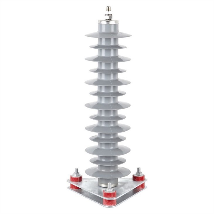
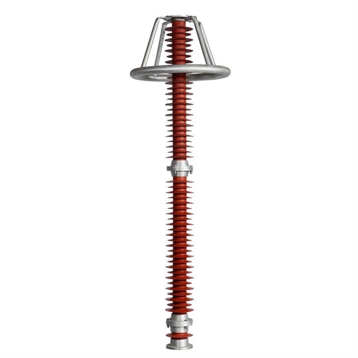
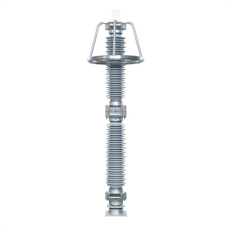
The products covers 35kV to 500kV porcelain-housed MOA, 6kV to 500kV polymeric MOA and 35kV to 500kV poly meric line type MOA with series gaps, are used to protect high-voltage equipment in substations, such as transformers, circuit breakers, and bushings, against the effects of overvoltages caused by incoming surges. Such overvoltages can be caused by a direct or nearby lightning strike, an electromagnetic pulse, electrostatic discharge, or switching operations in the power supply system as well as in devices. Some overvoltages are very high in energy. The current from the surge is diverted through the arrester, in most cases to earth. Effective overvoltage protection requires different surge arrester types to be used according to the particular application.
Applied Standards:
• GB 11032 Metal-oxde surge arresters without gaps for AC systems;
• GB/T 16434 High voltage overhead line and power station, transmission substation environmental pollution ares grading and external insulation choice standards;
• JB/T 7617 sf6 Type metal-oxide surge arresters without gaps;
•JB.T8952 Polymer-housed metal oxide surge arresters without gaps for AC systems;
• JB/T 10497 Polymeric housed metal oxide surge arresters with series gap for AC electric power tansmission line;
• IEC 60099-4 Metal-oxide surge arresters without gaps for AC systems
Part Ⅰ: Working Condition
Ambient air temperature: -40°C- + 40°C;
Altitude: S: 2000m;
Frequency: 48Hz-62Hz;
Power frequency voltage applied between terminals of surge arrester must not exceed continuous operating voltage of surge arrester;
Earthquake intensity is less than 8 degree;
Max. wind speed is 35m/s.
Part Ⅱ: Main Characteristics
Superior protective performance:
The metal oxide resistors made by possesses superior nonlinear volt-ampere characteristics and high energy capacity, making a great protective margin of discharge voltages at steep, lightning and switching current surges, and have remarkable effect for limiting overvoltage.
Reliable sealing performance:
During the whole MOA service life, the reliable sealing is ensured by application of weatherproof materials specific sealing design, slight positive pressure design patented and high-sensitive helium mass spectrometric detecting technology.
Excellent ageing performance:
superior ageing-proof performance, high overvoltage absorption capability, stable electrical characteristics, resulting to reliable service peformance.
Secure pressure relief capability:
Pressure relief device, specially designed for power utilities, has reliable pressure relief capability which ensures safe relief inner pressure of MOA in event of failure to prevent anyother failure.
High mechanical strength:
The bending stress of the produst surge arrest should be more than the stress of both the wire pulling and wind power, possessing more than 2.5 times allowance. The bending stress possess more than 1.67 times allowance relative to seismic force. The aseismatic products can stand 9 degree seismic intensity.
Continuous innovation and developmen:
Aiming at worldwide trend of MOA development, constantly devotes herself to development of Hi-tech MOA making us a top-ranking MOA manufacturer capable of supplying MOA of most complete varieties and superior performance in China.
Part Ⅲ: Electrical Characteristics – Phase Arresters for 35kV ~ 500kV Porcelain Housed MOA for AC. System
Usys kVcm․s | Type | Ur kVcm․s | UCCA kVcm․s | Ures ≤kVp | UImA ≥kV | Uref ≥kVcm․s | I2ms A | Lspec mm/kv | H mm | D mm | Weight kg | Units number | Fig No. | ||
1/10 | 8/20 | 30/60 | |||||||||||||
35 | Y5W-51/134W | 51 | 40.8 | 154 | 134 | 114 | 73.0 | 51 | 400 | 31 | 1005 | 250 | 78 | 1 | Fig1 |
35 neutral | Y1.5W-30/80W | 30 | 24 | / | 80 | 75 | 44 | 30 | 400 | 31 | 1005 | 250 | 78 | 1 | Fig1 |
66 | Y5W-84/221W | 84 | 67.2 | 254 | 221 | 188 | 121 | 84 | 600, 800 | 25/31 | 1704/1835 | 310 | 176/202 | 1 | Fig1 |
Y5W-90/235W | 90 | 72.5 | 270 | 235 | 201 | 130 | 90 | 600, 800 | |||||||
Y10W-90/235W | 90 | 72.5 | 264 | 235 | 201 | 130 | 90 | 600, 800 | |||||||
110 | Y10W-96/250W | 96 | 75 | 280 | 250 | 213 | 140 | 96 | 600, 800 | 25/31 | 1704/1835 | 310 | 176/202 | 1 | Fig1 |
Y10W-100/260W | 100 | 78 | 291 | 260 | 221 | 145 | 100 | 600, 800 | |||||||
Y10W-102/266W | 102 | 79.6 | 297 | 266 | 226 | 148 | 102 | 600, 800 | |||||||
Y10W-108/281W | 108 | 84 | 315 | 281 | 239 | 157 | 108 | 600, 800 | |||||||
110 neutral | Y1.5W-60/144W | 60 | 48 | / | 144 | 135 | 85 | 60 | 400 | 25/31 | 1005 | 250 | 78/82 | 1 | Fig1 |
Y1.5W-72/186W | 72 | 58 | / | 186 | 174 | 103 | 72 | 400 | |||||||
220 | Y10W 192/500W | 192 | 150 | 560 | 500 | 426 | 280 | 192 | 600, 800 | 25/31 | 3138/3400 | 850 | 400/412 | 2 | Fig2 |
Y10W 200/520W | 200 | 156 | 582 | 520 | 442 | 290 | 200 | 600, 800 | |||||||
Y10W-204/532W | 204 | 159 | 594 | 532 | 452 | 296 | 204 | 600, 800 | |||||||
Y10W-216/562W | 216 | 168.5 | 630 | 562 | 478 | 314 | 216 | 600, 800 | |||||||
220 neutral | Y1.5W-144/320W | 144 | 116 | / | 320 | 299 | 205 | 144 | 400, 600 | 25 | 1835 | 310 | 202 | 1 | Fig1 |
330 | Y10W-288/698W | 288 | 219 | 782 | 698 | 593 | 408 | 288 | 1200 | 25/31 | 3732/3992 | 1120 | 580/ | 2 | Fig3 |
Y10W-312/760W | 312 | 237 | 847 | 760 | 643 | 442 | 312 | 1200 | |||||||
330 neutral | Y1.5W-207/440W | 207 | 166 | / | 440 | 410 | 292 | 207 | 600 | 31 | 3400 | 850 | 412 | 2 | Fig2 |
500 | Y20W-420/1046W | 420 | 318 | 1170 | 1046 | 858 | 565 | 420 | 2000, 2500 | 25/31 | 5856/6111 | 1500 | 1555/1650 | 3 | Fig4 |
Y20W-444/1106W | 444 | 324 | 1238 | 1106 | 907 | 597 | 444 | 2000, 2500 | |||||||
Y20W-468/1166W | 468 | 330 | 1306 | 1166 | 956 | 630 | 468 | 2000, 2500 | |||||||
500 neutral | Y1.5W-102/260W | 102 | 155 | / | 260 | 243 | 82 | 102 | 600 | 31 | 1835 | 310 | 202 | 1 | Fig1 |
Y1.5W-96/260W | 96 | 157 | / | 260 | 243 | 77 | 96 | 600 | |||||||
750 | Y20W-600/1380W | 600 | 462 | 1518 | 1380 | 1142 | 810 | 600 | 2500 | 25/31 | 8024/8884 | 2500 | 2353/2553 | 4 | Fig5 |
Y20W-648/1491W | 648 | 498 | 1639 | 1491 | 1226 | 875 | 648 | 2500 | |||||||
1000 | Y20W-828/1620W | 828 | 658 | 1782 | 1620 | 1460 | 1130 (4mA) | 828 | 8800 | 25 | 11600 | 3800 | 6300 | 5 | Fig6 |

Electrical Characteristics – Phase Arresters for Polymeric MOA for AC. System
A) Typical technical parameters and outline dimensions of 6kV~ 500kV station and distribution type polymeric gapless MOA
Usys kVcm․s | Type | Ur kVcm․s | UCCA kVcm․s | Ures ≤kVp | UImA ≥kV | Uref ≥kVcm․s | I2ms A | Lspec mm/kv | H mm | D mm | Weight kg | Units | Fig No. | ||
1/10 | 8/20 | 30/60 | |||||||||||||
6 | YH5WS-10/30W | 10 | 8 | 34.6 | 30 | 25.6 | 15 | 10 | 100 | 31 | 257 | 106 | 3 | 1 | Fig16 |
YH5WZ-10/27W | 10 | 8 | 31 | 27 | 23 | 14.4 | 10 | 150 | |||||||
10 | YH5WS-17/50W | 17 | 13.6 | 57.5 | 50 | 42.5 | 25 | 17 | 100 | 31 | 257 | 106 | 2 | 1 | Fig16 |
YH5WZ-17/45W | 17 | 13.6 | 51.8 | 45 | 38.3 | 24 | 17 | 150 | |||||||
35 | YH5W-51/134W | 51 | 40.8 | 154 | 134 | 114 | 73 | 51 | 400 | 31 | 682 | 140 | 15 | 1 | Fig17 |
35 neutral | LYH1.5W-30/80W | 30 | 24 | / | 80 | 75 | 44 | 30 | 400 | 31 | 1005 | 250 | 78 | 1 | Fig1 |
66 | YH5W-84/221W | 84 | 67.2 | 254 | 221 | 188 | 121 | 84 | 600, 800 | 31 | 1264 | 220 | 62 | 1 | Fig18 |
YH10W-90/235W | 90 | 72.5 | 264 | 235 | 201 | 130 | 90 | 600, 800 | |||||||
110 | YH10W-100/260W | 100 | 78 | 291 | 260 | 221 | 145 | 100 | 600, 800 | 31 | 1264 | 220 | 62 | 1 | Fig18 |
YH10W-102/266W | 102 | 79.6 | 297 | 266 | 226 | 148 | 102 | 600, 800 | |||||||
YH10W-108/281W | 108 | 84 | 315 | 281 | 239 | 157 | 108 | 600, 800 | |||||||
110 neutral | YH1.5W-60/144W | 60 | 48 | / | 144 | 135 | 85 | 60 | 400 | 31 | 949 | 184 | 32 | 1 | Fig18 |
YH1.5W-72/186W | 72 | 58 | / | 186 | 174 | 103 | 72 | 400 | |||||||
220 | YH10W 200/520W | 200 | 156 | 582 | 520 | 442 | 290 | 200 | 600, 800 | 31 | 2335 | 850 | 124 | 2 | Fig20 |
YH10W-204/532W | 204 | 159 | 594 | 532 | 452 | 296 | 204 | 600, 800 | |||||||
YH10W-216/562W | 216 | 168.5 | 630 | 562 | 478 | 314 | 216 | 600, 800 | |||||||
220 neutral | YH1.5W-144/320W | 144 | 116 | / | 320 | 299 | 205 | 144 | 400 | 31 | 1856 | 184 | 65 | 2 | Fig19 |
330 | YH10W-288/698W | 288 | 219 | 782 | 698 | 593 | 408 | 288 | 1200 | 31 | 3530 | 362 | 450 | 2 | Fig21 |
YH10W-300/727 | 300 | 228 | 814 | 727 | 618 | 425 | 300 | 1200 | 31 | ||||||
YH10W-306/742 | 306 | 233 | 831 | 742 | 630 | 435 | 306 | 1200 | 31 | ||||||
YH10W-312/760W | 312 | 237 | 847 | 760 | 643 | 442 | 312 | 1200 | 31 | ||||||
YH10W-324/789W | 324 | 246 | 880 | 789 | 668 | 459 | 324 | 1200 | 31 | ||||||
330 neutral | YH1.5W-207/440W | 207 | 166 | / | 440 | 410 | 292 | 207 | 600 | 31 | 2335 | 220 | 124 | 2 | Fig20 |
500 | YH20W-420/1046W | 420 | 318 | 1170 | 1046 | 858 | 565 | 420 | 2000 | 31 | 5000 | 362 | 662 | 3 | Fig22 |
YH20W-444/1106W | 444 | 324 | 1238 | 1106 | 907 | 597 | 444 | 2000 | |||||||
YH20W-468/1166W | 468 | 330 | 1306 | 1166 | 956 | 630 | 468 | 2000 | |||||||
500 neutral | YH1.5W-102/260W | 102 | 82 | / | 260 | 243 | 155 | 102 | 600 | 31 | 1264 | 220 | 62 | 1 | Fig18 |
YH1.5W-96/260W | 96 | 77 | / | 260 | 243 | 137 | 96 | 600 | |||||||

B) Typical technical parameters and outline dimensions of 35kV 500kV line protection polymeric gapless MOA
Usys kVcm․s | Type | Ur kVcm․s | UCCA kVcm․s | Ures ≤kVp | UImA ≥kV | Uref ≥kVcm․s | I2ms A | Lspec mm/kv | H | D mm | Weight kg | Units | Fig No. | ||
1/10 | 8/20 | 30/60 | |||||||||||||
35 | YH5WX-51/134W | 51 | 40.8 | 154 | 134 | 114 | 73 | 51 | 400 | 31 | 661 | 140 | 13 | 1 | Fig23 |
66 | YH10WX-96/250W | 96 | 75 | 288 | 250 | 213 | 140 | 96 | 600, 800 | 31 | 1256 | 210 | 48 | 1 | Fig24 |
110 | YH10WX-108/281W | 108 | 84 | 315 | 281 | 239 | 157 | 108 | 600, 800 | 31 | 1256 | 210 | 48 | 1 | Fig24 |
YH10WX-114/297W | 114 | 89 | 341 | 297 | 252 | 165 | 114 | 600, 800 | |||||||
220 | YH10WX-216/562W | 216 | 168.5 | 630 | 562 | 478 | 314 | 216 | 600, 800 | 31 | 2472 | 850 | 99 | 2 | Fig25 |
330 | YH10WX-312/760W | 312 | 237 | 847 | 760 | 643 | 442 | 312 | 1200 | 25 | 3630 | 1200 | 256 | 3 | Fig26 |
YH10WX-324/789W | 324 | 246 | 880 | 789 | 668 | 459 | 324 | 1200 | |||||||
500 | YH20WX-444/1106W | 444 | 324 | 1238 | 1106 | 907 | 597 | 444 | 1800 | 25 | 5098 | 2000 | 405 | 3 | Fig27 |
YH20WX-468/1166W | 468 | 330 | 1306 | 1166 | 956 | 630 | 468 | 1800 | |||||||

C) Typical technical parameters and outline dimensions of 35kV 500kV polymeric with series gaps MOA
Usys kVcm․s | Type | MOA body | MOA | Hmm | D mm | Weight kg | Units | Fig No. | Remark | |||||||
Ur kVcm․s | Ures ≤kVp | UImA ≥kV | Uref ≥kVcm․s | I2ms A | lmin ≥kVcm․s | Uinpspv ≥kVcm․s | Gap spac emm | |||||||||
1/10 | 8/20 | |||||||||||||||
35 | YH5CX-42/120 | 42 | 132 | 120 | 60 | 42 | 250 | 82 | 240 | 220±20 | 661 | 140 | 20 | 1 | Fig29 | Air gap Insulator support clearance |
110 | YH10CX-84/220 | 84 | 252 | 220 | 123 | 84 | 400 | 185 | 525 | 550±50 | 1100/ | 168 | 39/46 | 1 | Fig29 | Air gap Insulator support clearance |
YH10CX-90/260 | 90 | 292 | 260 | 130 | 90 | 400 | ||||||||||
YH10CX-96/280 | 96 | 314 | 280 | 140 | 96 | 400 | ||||||||||
YH10CX-108/256 | 108 | 358 | 320 | 160 | 108 | 400 | ||||||||||
220 | YH10CX-180/520 | 168 | 584 | 520 | 260 | 168 | 600 | 370 | 900 | 900±50 | 2100/ | 168 | 72/85 | 2 | Fig31 | Air gap Insulator support clearance |
YH10CX-192/560 | 192 | 628 | 560 | 280 | 192 | 600 | ||||||||||
YH10CX-216/640 | 216 | 716 | 640 | 320 | 216 | 600 | ||||||||||
500 | YH20CX-396/1050 | 396 | 1171 | 1050 | 561 | 396 | 1200 | 567 | 1760 | 1650±150 | 3738/ | 249 | 292 | 3 | Fig33 | Air gap Insulator support clearance |
YH20CX-396/1050 | 396 | 1171 | 1050 | 561 | 396 | 1200 | ||||||||||

Typical technical parameters and outline dimensions of gapless MOA for electrified railway protection
Usys kVcm․s | Type | Ur kVcm․s | UCCA kVcm․s | Ures ≤kVp | UImA ≥kV | Uref ≥kVcm․s | I2ms A | Lspec mm/kv | H mm | D mm | Weight kg | Units | Fig No. | ||
1/10 | 8/20 | 30/60 | |||||||||||||
27.5 | Y5WT-42/120W | 42 | 34 | 138 | 120 | 98 | 65 | 42 | 400 | 31 | 1005 | 250 | 78 | 1 | Fig1 |
T10WT-42/140W | 42 | 34 | 157 | 140 | 119 | 65 | 42 | 400 | |||||||
YH5WT-42/120W | 42 | 34 | 138 | 120 | 98 | 65 | 42 | 400 | 31 | 682 | 140 | 15 | 1 | Fig18 | |
YH10WT-42/105 | 42 | 31.5 | 118 | 105 | 89 | 58 | 40 | 400 | 31 | 562 | 150 | 17 | Fig18 | ||
55 | Y5WT-84/240W | 84 | 68 | 276 | 240 | 196 | 130 | 84 | 400 | 31 | 1835 | 310 | 202 | 1 | Fig1 |
Y10WT-84/260W | 84 | 68 | 291 | 260 | 221 | 130 | 84 | ||||||||
YH5WT-84/240W | 84 | 68 | 276 | 240 | 196 | 130 | 84 | 600 | 1264 | 220 | 62 | Fig18 | |||
YH10WT-84/240W | 84 | 68 | 276 | 240 | 196 | 130 | 84 | ||||||||
110 | Y5WT-100/260W | 100 | 78 | 299 | 260 | 221 | 145 | 100 | 600 | 31 | 1835 | 310 | 202 | 1 | Fig1 |
Y10WT-100/275W | 100 | 73 | 316 | 275 | 234 | 145 | 100 | ||||||||
YH5WT-100/260W | 100 | 78 | 299 | 260 | 221 | 145 | 100 | 800 | 1264 | 220 | 62 | Fig18 | |||
YH10WT-100/275W | 100 | 73 | 316 | 275 | 234 | 145 | 100 | ||||||||
Typical technical parameters and outline dimensions of MOA for protecting electric rotating machines
Destination | Type | Ur kVcm․s | UCCA kVcm․s | Ures ≤kVp | UImA ≥kV | Uref ≥kVcm․s | I2ms A | ||
1/10 | 8/20 | 30/60 | |||||||
Generator | YH5W-4/9.5 | 4 | 3.2 | 10.7 | 9.5 | 7.6 | 5.7 | 3.8 | 400 |
YH5W-8/18.7 | 8 | 6.3 | 21 | 18.7 | 15 | 11.2 | 7.7 | ||
YH5W-13.5/31 | 13.5 | 10.5 | 34.7 | 31 | 25 | 18.6 | 13 | ||
YH5W-17.5/40 | 17.5 | 13.8 | 44.8 | 40 | 32 | 24.4 | 17 | ||
YH5W-20/45 | 20 | 15.8 | 50.4 | 45 | 36 | 28 | 19.5 | ||
YH5W-23/51 | 23 | 18.0 | 57.2 | 51 | 40.8 | 31.9 | 21.9 | ||
YH5W-25/56.2 | 25 | 20.0 | 62.9 | 56.2 | 45.0 | 35.4 | 24.3 | ||
Motor | YH2.5W-4/9.5 | 4 | 3.2 | 10.7 | 9.5 | 7.6 | 5.7 | 3.8 | 400 |
YH2.5W-8/18.7 | 8 | 6.3 | 21 | 18.7 | 15 | 11.2 | 7.7 | ||
YH2.5W-13.5/31 | 13.5 | 10.5 | 34.7 | 31 | 25 | 18.6 | 13 | ||
Neutral of electric machine | YH1.5W-2.4/6 | 2.4 | 1.9 | - | 6.0 | 5.0 | 3.4 | 2.4 | 400 |
YH1.5W-4.8/12 | 4.8 | 3.8 | - | 12.0 | 10.0 | 6.8 | 4.8 | ||
YH1.5W-8/19 | 8 | 6.4 | - | 19.0 | 15.9 | 11.4 | 8 | ||
YH1.5W-10.5/23 | 10.5 | 8.4 | - | 23.0 | 19.2 | 14.9 | 10.5 | ||
YH1.5W-12/26 | 12 | 9.6 | - | 26.0 | 21.6 | 17.0 | 12 | ||
YH1.5W-13.7/29.2 | 13.7 | 11.0 | - | 29.2 | 24.3 | 19.5 | 13.7 | ||
YH1.5W-15.2/31.7 | 15.2 | 12.2 | - | 31.7 | 26.4 | 21.6 | 15.2 | ||
Typical technical parameters and outline dimensions of gapless MOA for shunt compensation capacitor bank
Usys kVcm․s | Type | Ur kVcm․s | UCCA kVcm․s | Ures ≤kVp | UImA ≥kV | Uref ≥kVcm․s | I2ms A | Lspec mm/kv | H mm | D mm | Weight kg | Units | Fig No. | |
8/20 | 30/60 | |||||||||||||
6 | YH5WR-10/27W | 10 | 8.0 | 27.0 | 21.0 | 14.4 | 10 | 400 | 31 | 297 | 108 | 3 | 1 | Fig16 |
10 | YH5WR-12/32.4W | 12 | 9.6 | 32.4 | 25.2 | 17.4 | 12 | 400 | 31 | 297 | 108 | 3.4 | 1 | Fig16 |
YH5WR-15/40.5W | 15 | 12.0 | 40.5 | 31.5 | 21.8 | 15 | ||||||||
YH5WR-17/46W | 17 | 13.6 | 46 | 35 | 24 | 17 | ||||||||
35 | YH5WR-51/134W | 51 | 40.8 | 134 | 105 | 73 | 51 | 400-2500 | 31 | 682 | 140 | 15 | 1 | Fig18 |
YH10WR-52.7/134W | 52.7 | 42.2 | 134 | 105 | 74.5 | 52.7 | 680 | 210 | 34 | |||||
YH10WR-54/134W | 54 | 43.2 | 134 | 105 | 76 | 54 | 844 | 238 | 54 | |||||
Y5WR-51/134W | 51 | 40.8 | 134 | 105 | 73 | 51 | 400-2500 | 31 | 1005 | 250 | 78 | 1 | Fig1 | |
Y10WR-52.7/134W | 52.7 | 42.2 | 134 | 105 | 74.5 | 52.7 | 1175 | 290 | 140 | |||||
Y10WR-54/134W | 54 | 43.2 | 134 | 105 | 76 | 54 | 1192 | 345 | 205 | |||||
110 | Y10WR-84/221W | 84 | 67.2 | 221 | 176 | 121 | 84 | 600-2000 | 25/31 | 1704 | 310 | 176 | 1 | Fig1 |
Y10WR-90/236W | 90 | 72.5 | 236 | 190 | 130 | 90 | 2032 | 351 | 202 | |||||
Technical parameters for static Var compensation device (SVC) of Complete MOA
Usys kVcm․s | Type | Ur kVcm․s | UCCA kVcm․s | UImA ≥kV | Uref ≥kVcm․s | I2ms A | Ures ≤kVp 8/20 |
35 | Y0.5WR-45/106 | 45 | 41.26 | 76.4 | 45 | 600 | 106 |
Y0.5WR-45/110 | 45 | 38.8 | 76.3 | 45 | 1200 | 110 | |
Y0.5WR-42/98.7 | 42 | 34.8 | 69.6 | 42 | 600 | 98.7 | |
Y0.5WR-36/81.6 | 36 | 28.36 | 56.6 | 36 | 600 | 81.6 | |
Y0.5WR-42/92 | 42 | 23 | 60 | 42 | 600 | 92 | |
Y0.5WR-24/56.2 | 24 | 23 | 37.8 | 24 | 600 | 56.2 |
Technical parameters of monitors
Usys kVcm․s | Type | In 8/20 kAp | Id 8/20 Ap | I2ms Ap | High cur. kAp | Ures ≤kVp | Basic scale mAcm․s | Weight kg |
6-220 | JCQ3A-10/800 | 10 | 50 | 800 | 100 | 1.5 | 0-2 | 3 |
330 | JCQ3A-10/1500 | 10 | 50 | 1500 | 100 | 1.5 | 0-5 | 3 |
500 | JCQ3A-20/2000 | 20 | 50 | 2000 | 20 | 50 | 0-5 | 3 |
750 | JCQ3C-20/2500 | 20 | 50 | 2500 | 20 | 50 | 0-6 (Wide angle) | 3.5 |

Hot Tags: 6kv to 500kv outdoor hv ac surge arrest, China, suppliers, manufacturers, factory, price, made in China