Part Ⅰ: Resin Insulated Dry Type Transformers Overview
Resin insulated dry type transformers by epoxy resin insulation, the product has flame retardant, low loss, low noise, low local discharge, good mechanical strength, safe and reliable, generally installed in the distribution room or box-type substation, as lighting or power supply with a capacity of 31500kVA and below.
Amorphous alloy core dry type transformers of 10kV level and below | |
Product Attributes | |
Model No. | SG9/SG10 |
Application | Power |
Coil | Core-type Transformer |
Frequency | 50/60Hz |
Phase | Three |
Cooling Method | Dry-type Transformer |
Max. Ambient Temperature | +40 °C |
Max.daily average ambient temperature | +30°C |
Max.annual average ambient temperature | +20°C |
Min. temperature | -5°C ( indoor installation) |
Operating Altitude | ≤1000m |
Standard | IEC 60076-11 :2004; ANSI, etc |
Supply Ability & Additional Information | |
Packaging | Seaworthy Packing |
Transportation | Ocean |
Supply Ability | High |
Payment Type | L/C, T/T |
Delivery Time | 60 Days |
Productivity | 300 sets/year |
Place of Origin | China |
Certificate | ISO |
Port | China Sea Port |
Incoterm | FOB, CFR, CIF |
Packaging & Delivery | |
Selling Units: | Set/Sets |
Package Type: | Seaworthy Packing |
Part Ⅱ: Product Features
1. Low Noise
① Normal operation noise is less than 58 decibels
② Selecting high quality core material, choosing suitable magnetic flux density and self-vibration frequency of core.
2. Low Loss
① Adopt magnetic leakage calculation and take effective measures to reduce stray losses, while effectively preventing local overheating and reducing the temperature rise of winding hot spots.
② Reasonable selection of coil wires to reduce winding eddy current loss, stray loss and other additional losses.
3. Low Partial discharge
The solid insulation made of high quality resin and glass fiber has high electrical strength and the partial discharge is very small and can be controlled within ≤5pC
4. Flame retardant
① Under the burning of high temperature open flame, transformer almost no smoke generated
② Burning grade F1
5. High overload capacity
Can be operated for long-term cyclic load or temporary emergency type load.
6. Strong short circuit resistance
① The high voltage coil adopts resin casting structure, with good mechanical strength.
② Adopting pulling plate and gasket pressing structure, which makes the whole body stable and firm.
Part Ⅲ: Structure Feature
1. Iron Core
The iron core is made of high quality, cold-rolled, granule-oriented silicon-steel sheets and machined with completely automatic cutting line, superposed with 45° six-level bias seams. Core column adopts special banding technique, the surface of iron core is painted with the special rustproof coating to resist humidity and rust, which can effectively reduce the no-load losses, no-load current and iron-core noise. Facilitated with six sets of cutting lines for iron core such as, Soenen from Belgium.

2. Winding
F-class insulation HV winding: it is made of lacquered wire. With hardness ranges from 120 to 210 Mpa. The insulation material is a composite of silicon micro-powder and epoxy resin, featuring high performances of good thermal shock resistance, fire resistance, no emission of hazardous gases, good heat dispersion and low winding temperature rise.

H-class insulation HV winding: it adopts NOMEX paper wrapped flat copper wire and continuous winding process. The winding made after dry treatment by VPI vacuum pressure device, several times impregnated in special H class insulating paint.and baking features high mechanical strength, good heat dispersion.

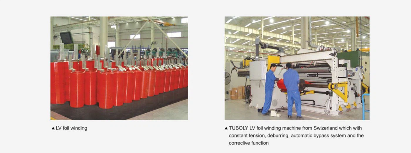
LV winding: LV winding is mainly made of foils. It adopts interior argon gas protection welding,with high precision and reliability as no external welding joint. It solves the winding turns imbalance , effectively improves thermal performance and enhance short circuit withstanding capability.
Part Ⅲ: Product Main Parameter
9 Series 10kV Free Excitation Voltage Regulation Distribution Transformer | ||||||||
Model | Voltage Combination | Conneciton | No Load Losses (W) | Load Loss under F class (W) | No Load Current (%) | Short-circuit Impedance | ||
HV | HV Tap | LV | ||||||
SC9-30 | 6; 6.3; 6.6; 10; 10.5; 11 | ±5/±2×2.5 | 0.4 | Dyn11/Yyn0 | 220 | 750 | 2.4 | 4 |
SC9-50 | 310 | 1060 | 2.4 | |||||
SC9-80 | 420 | 1460 | 1.8 | |||||
SC9-100 | 450 | 1670 | 1.8 | |||||
SC9-125 | 530 | 1960 | 1.6 | |||||
SC9-160 | 610 | 2250 | 1.6 | |||||
SC(B)9-200 | 700 | 2680 | 1.4 | |||||
SC(B)9-250 | 810 | 2920 | 1.4 | |||||
SC(B)9-315 | 990 | 3670 | 1.2 | |||||
SC(B)9-400 | 1100 | 4220 | 1.2 | |||||
SC(B)9-500 | 1310 | 5170 | 1.2 | |||||
SC(B)9-630 | 1510 | 6220 | 1 | |||||
SC(B)9-630 | 1460 | 6310 | 1 | 6 | ||||
SC(B)9-800 | 1710 | 7360 | 1 | |||||
SC(B)9-1000 | 1990 | 8610 | 1 | |||||
SC(B)9-1250 | 2350 | 10260 | 1 | |||||
SC(B)9-1600 | 2760 | 12400 | 1 | |||||
SC(B)9-2000 | 3400 | 15300 | 0.8 | |||||
SC(B)9-2500 | 4000 | 18180 | 0.8 | |||||
SC(B)9-1600 | 2760 | 13700 | 1 | 8 | ||||
SC(B)9-2000 | 3400 | 16900 | 0.8 | |||||
SC(B)9-2500 | 4000 | 20000 | 0.8 | |||||
10 Series 10kV Free Excitation Voltage Regulation Distribution Transformer | ||||||||
Model | Voltage Combination | Conneciton | No Load Losses (W) | Load Loss under F class (W) | No Load Current (%) | Short-circuit Impedance | ||
HV | HV Tap | LV | ||||||
SC10-30 | 6; 6.3; 6.6; 10; 10.5; 11 | ±5/±2×2.5 | 0.4 | Dyn11/Yyn0 | 190 | 710 | 2.4 | 4 |
SC10-50 | 270 | 1000 | 2.4 | |||||
SC10-80 | 370 | 1380 | 1.8 | |||||
SC10-100 | 400 | 1570 | 1.8 | |||||
SC10-125 | 470 | 1850 | 1.6 | |||||
SC10-160 | 540 | 2130 | 1.6 | |||||
SC(B)10-200 | 620 | 2530 | 1.4 | |||||
SC(B)10-250 | 720 | 2760 | 1.4 | |||||
SC(B)10-315 | 880 | 3470 | 1.2 | |||||
SC(B)10-400 | 980 | 3990 | 1.2 | |||||
SC(B)10-500 | 1160 | 4880 | 1.2 | |||||
SC(B)10-630 | 1340 | 5880 | 1 | |||||
SC(B)10-630 | 1300 | 5960 | 1 | 6 | ||||
SC(B)10-800 | 1520 | 6960 | 1 | |||||
SC(B)10-1000 | 1770 | 8130 | 1 | |||||
SC(B)10-1250 | 2090 | 9690 | 1 | |||||
SC(B)10-1600 | 2450 | 11730 | 1 | |||||
SC(B)10-2000 | 3050 | 14450 | 0.8 | |||||
SC(B)10-2500 | 3600 | 17170 | 0.8 | |||||
SC(B)10-1600 | 2450 | 12960 | 1 | 8 | ||||
SC(B)10-2000 | 3050 | 15960 | 0.8 | |||||
SC(B)10-2500 | 3600 | 18890 | 0.8 | |||||
9 Series 20kV Free Excitation Voltage Regulation Distribution Transformer | ||||||||
Model | Voltage Combination | Conneciton | No Load Losses (W) | Load Loss under F class (W) | No Load Current (%) | Short-circuit Impedance | ||
HV | HV Tap | LV | ||||||
SC9-50 | 20; 22; 24 | ±5/±2×2.5 | 0.4 | Dyn11/Yyn0 | 380 | 1300 | 2.4 | 6 |
SC9-100 | 600 | 2100 | 2.2 | |||||
SC9-160 | 750 | 2600 | 1.8 | |||||
SC(B)9-200 | 820 | 3100 | 1.8 | |||||
SC(B)9-250 | 940 | 3600 | 1.6 | |||||
SC(B)9-315 | 1080 | 4300 | 1.6 | |||||
SC(B)9-400 | 1280 | 5100 | 1.4 | |||||
SC(B)9-500 | 1500 | 6100 | 1.4 | |||||
SC(B)9-630 | 1700 | 7200 | 1.2 | |||||
SC(B)9-800 | 1950 | 8700 | 1.2 | |||||
SC(B)9-1000 | 2300 | 10300 | 1 | |||||
SC(B)9-1250 | 2650 | 12150 | 1 | |||||
SC(B)9-1600 | 3100 | 14600 | 1 | |||||
SC(B)9-2000 | 3600 | 17250 | 0.8 | |||||
SC(B)9-2500 | 4300 | 20400 | 0.8 | 8 | ||||
SC(B)9-2000 | 3600 | 18800 | 0.8 | |||||
SC(B)9-2500 | 4300 | 22400 | 0.8 | |||||
10 Series 20kV Free Excitation Voltage Regulation Distribution Transformer | ||||||||
Model | Voltage Combination | Conneciton | No Load Losses (W) | Load Loss under F class (W) | No Load Current (%) | Short-circuit Impedance | ||
HV | HV Tap | LV | ||||||
SC -50 | 20; 22; 24 | ±5/±2×2.5 | 0.4 | Dyn11/Yyn0 | 345 | 1235 | 2.4 | 6 |
SC -100 | 540 | 1995 | 2.2 | |||||
SC -160 | 675 | 2470 | 1.8 | |||||
SC(B) -200 | 740 | 2945 | 1.8 | |||||
SC(B) -250 | 845 | 3420 | 1.6 | |||||
SC(B) -315 | 975 | 4085 | 1.6 | |||||
SC(B) -400 | 1155 | 4845 | 1.4 | |||||
SC(B) -500 | 1350 | 5795 | 1.4 | |||||
SC(B) -630 | 1530 | 6840 | 1.2 | |||||
SC(B) -800 | 1755 | 8265 | 1.2 | |||||
SC(B) -1000 | 2070 | 9785 | 1 | |||||
SC(B) -1250 | 2385 | 11545 | 1 | |||||
SC(B) -1600 | 2790 | 13870 | 1 | |||||
SC(B) -2000 | 3240 | 16390 | 0.8 | |||||
SC(B) -2500 | 3870 | 19380 | 0.8 | |||||
SC(B) -2000 | 3240 | 17860 | 0.8 | 8 | ||||
SC(B) -2500 | 3870 | 21280 | 0.8 | |||||
9 Series 35kV Free Excitation Voltage Regulation Distribution Transformer | ||||||||
Model | Voltage Combination | Conneciton | No Load Losses (W) | Load Loss under F class (W) | No Load Current (%) | Short-circuit Impedance | ||
HV | HV Tap | LV | ||||||
SC9-50 | 35~38.5 | ±5/±2×2.5 | 0.4 | Dyn11/Yyn0 | 500 | 1500 | 2.8 | 6 |
SC9-100 | 700 | 2200 | 2.4 | |||||
SC9-160 | 880 | 2960 | 1.8 | |||||
SC(B)9-200 | 980 | 3500 | 1.8 | |||||
SC(B)9-250 | 1100 | 4000 | 1.6 | |||||
SC(B)9-315 | 1310 | 4750 | 1.6 | |||||
SC(B)9-400 | 1530 | 5700 | 1.4 | |||||
SC(B)9-500 | 1800 | 7000 | 1.4 | |||||
SC(B)9-630 | 2070 | 8100 | 1.2 | |||||
SC(B)9-800 | 2400 | 9600 | 1.2 | |||||
SC(B)9-1000 | 2700 | 11000 | 1 | |||||
SC(B)9-1250 | 3150 | 13400 | 0.9 | |||||
SC(B)9-1600 | 3600 | 16300 | 0.9 | |||||
SC(B)9-2000 | 4250 | 19200 | 0.9 | |||||
SC(B)9-2500 | 4950 | 23000 | 0.9 | |||||
9 Series 35kV Free Excitation Voltage Regulation Distribution Transformer | ||||||||
Model | Voltage Combination | Conneciton | No Load Losses (W) | Load Loss under F class (W) | No Load Current (%) | Short-circuit Impedance | ||
HV | HV Tap | LV | ||||||
SC(B)9-800 | 35~38.5 | ±5/±2×2.5 | 3.15 | Dyn11 | 2500 | 9900 | 1.1 | 6 |
SC(B)9-1000 | 2970 | 11500 | 1.1 | |||||
SC(B)9-1250 | 3480 | 13600 | 1 | |||||
SC(B)9-1600 | 4100 | 16300 | 1 | |||||
SC(B)9-2000 | 4700 | 19200 | 0.9 | 7 | ||||
SC(B)9-2500 | 5400 | 23000 | 0.9 | |||||
SC(B)9-3150 | 6700 | 25800 | 0.8 | 8 | ||||
SC(B)9-4000 | 7800 | 31000 | 0.8 | |||||
SC(B)9-5000 | 9300 | 36800 | 0.7 | |||||
SC(B)9-6300 | 11000 | 43000 | 0.7 | |||||
SC(B)9-8000 | Dyn11 | 12600 | 48500 | 0.6 | ||||
SC(B)9-10000 | 14400 | 58500 | 0.6 | 9 | ||||
SC(B)9-12500 | 6 | 17500 | 68000 | 0.5 | ||||
SC(B)9-16000 | 21500 | 80000 | 0.5 | |||||
SC(B)9-20000 | 25500 | 90000 | 0.4 | 10 | ||||
Part Ⅳ: Structural Diagram
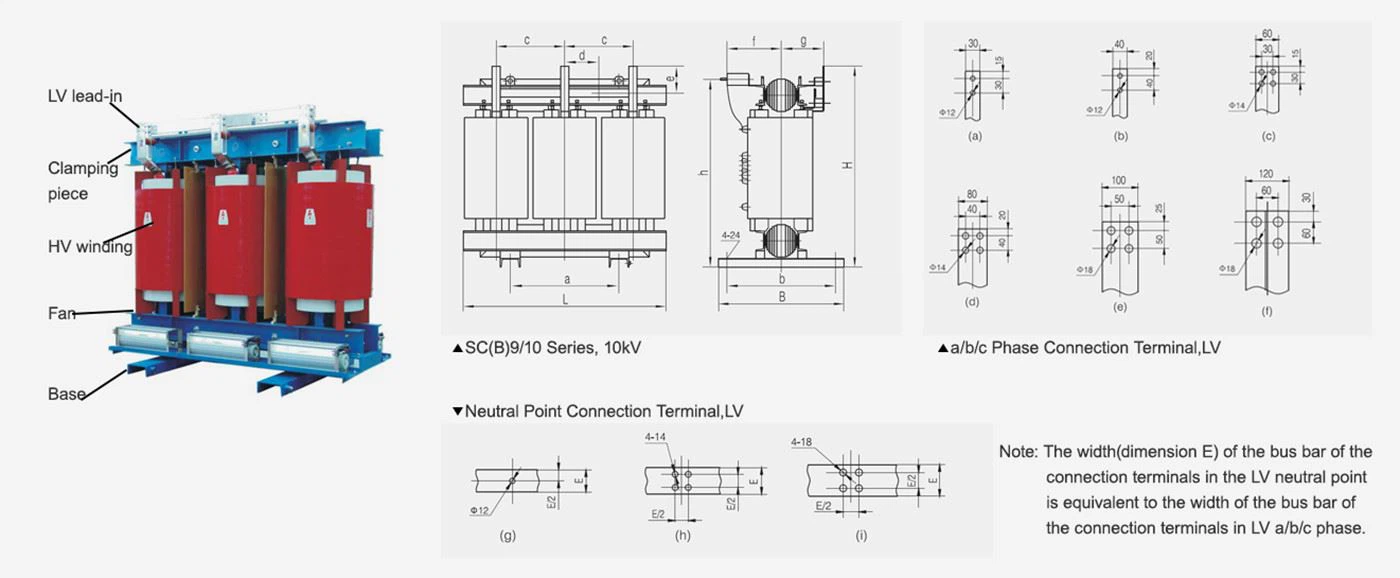
Dimension of Transformer Body of SC(B)9 Series, 10kV (unit: mm) | ||||||||||||||
Model | Short Circuit | Overall Dimension | Installation Dimension | c | d | e | f | g | h | LV Terminal | ||||
L | B | H | a | b | a/b/c Phase Neutral Point | |||||||||
SC9-30/10 | 4 | 870 | 500 | 935 | 400 | 400 | 290 | 145 | 175 | 275 | 185 | 850 | (a) | (g) |
SC9-50/10 | 900 | 500 | 955 | 400 | 400 | 305 | 150 | 175 | 280 | 190 | 875 | (a) | (g) | |
SC9-80/10 | 960 | 500 | 995 | 400 | 400 | 325 | 160 | 175 | 285 | 195 | 915 | (a) | (g) | |
SC9-100/10 | 990 | 650 | 1045 | 550 | 550 | 335 | 165 | 175 | 295 | 205 | 960 | (a) | (g) | |
SC9-125/10 | 1030 | 650 | 1060 | 550 | 550 | 350 | 175 | 175 | 300 | 210 | 980 | (a) | (g) | |
SC9-160/10 | 1060 | 650 | 1110 | 550 | 550 | 365 | 180 | 175 | 305 | 215 | 1030 | (a) | (g) | |
SC9-200/10 | 1180 | 760 | 1160 | 660 | 660 | 395 | 197.5 | 150 | 315 | 245 | 1070 | (a) | (g) | |
SC9-250/10 | 1200 | 760 | 1200 | 660 | 660 | 405 | 202.5 | 120 | 320 | 245 | 1110 | (a) | (g) | |
SC9-315/10 | 1280 | 760 | 1240 | 660 | 660 | 415 | 210 | 180 | 325 | 250 | 1145 | (b) | (g) | |
SC9-400/10 | 1300 | 760 | 1280 | 660 | 660 | 440 | 200 | 180 | 335 | 270 | 1200 | (c) | (h) | |
SC9-500/10 | 1360 | 920 | 1405 | 660 | 820 | 455 | 225 | 200 | 345 | 280 | 1305 | (d) | (h) | |
SC9-630/10 | 1500 | 920 | 1398 | 660 | 820 | 480 | 240 | 200 | 337 | 300 | 1298 | (d) | (h) | |
SC9-630/10 | 6 | 1525 | 920 | 1333 | 660 | 820 | 485 | 242.5 | 195 | 333 | 321 | 1233 | (d) | (h) |
SC9-800/10 | 1670 | 920 | 1393 | 660 | 820 | 530 | 265 | 195 | 342 | 334 | 1293 | (d) | (h) | |
SC9-1000/10 | 1660 | 920 | 1458 | 660 | 820 | 535 | 267.5 | 220 | 349 | 321 | 1358 | (d) | (h) | |
SC9-1250/10 | 1780 | 920 | 1628 | 820 | 820 | 560 | 280 | 225 | 360 | 347.5 | 1538 | (e) | (i) | |
SC9-1600/10 | 1850 | 1170 | 1658 | 1070 | 1070 | 600 | 300 | 240 | 369 | 360.2 | 1558 | (e) | (i) | |
SC9-2000/10 | 2070 | 1170 | 1766 | 1070 | 1070 | 660 | 325 | 265 | 387.5 | 382.5 | 1655.5 | (f) | (i) | |
SC9-2500/10 | 2100 | 1170 | 2160 | 1070 | 1070 | 695 | 347.5 | 275 | 497 | 438 | 2009.5 | (f) | (i) | |
Dimension of Transformer Body of SC(B) 10 Senes, 10kV (unit: mm) | ||||||||||||||
Model | Short Circuit | Overall Dimension | Installation Dimension | c | d | e | f | g | h | LV Terminal | ||||
L | B | H | a | b | a/b/c Phase Neutral Point | |||||||||
SC10-30/10 | 4 | 870 | 500 | 935 | 400 | 400 | 290 | 145 | 175 | 275 | 185 | 850 | (a) | (g) |
SC10-50/10 | 900 | 500 | 955 | 400 | 400 | 305 | 150 | 175 | 280 | 190 | 875 | (a) | (g) | |
SC10-80/10 | 960 | 500 | 995 | 400 | 400 | 325 | 160 | 175 | 285 | 195 | 915 | (a) | (g) | |
SC10-100/10 | 990 | 650 | 1045 | 550 | 550 | 335 | 165 | 175 | 295 | 205 | 960 | (a) | (g) | |
SC10-125/10 | 1030 | 650 | 1060 | 550 | 550 | 350 | 175 | 175 | 300 | 210 | 980 | (a) | (g) | |
SC10-160/10 | 1080 | 650 | 1110 | 550 | 550 | 365 | 180 | 175 | 305 | 215 | 1030 | (a) | (g) | |
SC10-200/10 | 1180 | 760 | 1160 | 660 | 660 | 395 | 197.5 | 150 | 315 | 245 | 1070 | (a) | (g) | |
SC10-250/10 | 1200 | 760 | 1200 | 660 | 660 | 405 | 202.5 | 120 | 320 | 245 | 1110 | (a) | (g) | |
SC10-315/10 | 1230 | 760 | 1240 | 660 | 660 | 415 | 210 | 180 | 325 | 250 | 1145 | (b) | (g) | |
SC10-400/10 | 1300 | 760 | 1280 | 660 | 660 | 440 | 200 | 180 | 335 | 270 | 1200 | (c) | (h) | |
SC10-500/10 | 1350 | 920 | 1405 | 660 | 820 | 455 | 225 | 200 | 345 | 280 | 1305 | (d) | (h) | |
SC10-630/10 | 1500 | 920 | 1398 | 660 | 820 | 480 | 240 | 200 | 337 | 300 | 1298 | (d) | (h) | |
SC10-630/10 | 6 | 1525 | 920 | 1333 | 660 | 820 | 485 | 242.5 | 195 | 333 | 321 | 1233 | (d) | (h) |
SC10-800/10 | 1640 | 920 | 1453 | 660 | 820 | 510 | 255 | 195 | 337 | 320 | 1353 | (d) | (h) | |
SC10-1000/10 | 1640 | 920 | 1520.5 | 660 | 820 | 530 | 265 | 220 | 342 | 340 | 1420.5 | (d) | (h) | |
SC10-1250/10 | 1780 | 920 | 1628 | 820 | 820 | 560 | 280 | 225 | 360 | 347.5 | 1538 | (e) | (i) | |
SC10-1600/10 | 1910 | 1170 | 1728 | 1070 | 1070 | 610 | 305 | 240 | 374 | 365 | 1638 | (e) | (i) | |
SC10-2000/10 | 2070 | 1170 | 1815.5 | 1070 | 1070 | 625 | 312.5 | 265 | 383 | 382.5 | 1705.5 | (f) | (i) | |
SC10-2500/10 | 2100 | 1170 | 2159.5 | 1070 | 1070 | 695 | 347.5 | 275 | 497 | 438 | 2009.5 | (f) | (i) | |
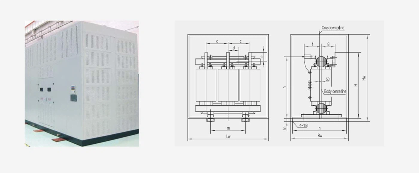
Dimension of Transformer Body of SC(B) 10 Senes, 10kV (unit: mm) | ||||||||||||||
Model | Short Circuit | Overall Dimension | Installation Dimension | c | d | e | f | g | h | H | hn | |||
Lw | Bw | Hw | m | n | ||||||||||
SC9, 10-125/10 | 4 | 1550 | 1150 | 1700 | 550 | 1090 | 350 | 175 | 175 | 300 | 210 | 980 | 1060 | 140 |
SC9, 10-160 /10 | 1550 | 1150 | 1700 | 550 | 1090 | 365 | 180 | 175 | 305 | 215 | 1030 | 1110 | 140 | |
SC(B)9, 10-200/10 | 1550 | 1150 | 1700 | 660 | 1090 | 395 | 197.5 | 150 | 315 | 245 | 1070 | 1160 | 140 | |
SC(B)9, 10-250/10 | 1550 | 1150 | 1700 | 660 | 1090 | 405 | 202.5 | 120 | 320 | 245 | 1110 | 1200 | 140 | |
SC(B)9, 10-315/10 | 1550 | 1150 | 1700 | 660 | 1090 | 415 | 210 | 180 | 325 | 250 | 1145 | 1240 | 140 | |
SC(B)9, 10-400/10 | 1700 | 1200 | 1750 | 660 | 1140 | 440 | 200 | 180 | 335 | 270 | 1200 | 1280 | 140 | |
SC(B)9, 10-500/10 | 1700 | 1200 | 1750 | 660 | 1140 | 455 | 225 | 200 | 345 | 280 | 1305 | 1405 | 140 | |
SC(B)9, 10-630/10 | 1700 | 1200 | 1750 | 660 | 1140 | 455 | 210 | 200 | 345 | 290 | 1305 | 1405 | 140 | |
SC(B)9, 10-630/10 | 6 | 1800 | 1300 | 1900 | 660 | 1240 | 485 | 225 | 195 | 340 | 280 | 1315 | 1415 | 140 |
SC(B)9, 10-800/10 | 1800 | 1300 | 1900 | 660 | 1240 | 500 | 250 | 195 | 345 | 280 | 1380 | 1480 | 140 | |
SC(B)9, 10-1000/10 | 1900 | 1300 | 2000 | 660 | 1240 | 520 | 260 | 220 | 350 | 290 | 1445 | 1575 | 140 | |
SC(B)9, 10-1250/10 | 1950 | 1400 | 2100 | 820 | 1340 | 540 | 270 | 225 | 350 | 290 | 1625 | 1740 | 140 | |
SC(B)9, 10-1600/10 | 2100 | 1500 | 2200 | 1070 | 1440 | 570 | 285 | 240 | 365 | 305 | 1660 | 1790 | 140 | |
SC(B)9, 10-2000/10 | 2250 | 1500 | 2300 | 1070 | 1440 | 605 | 300 | 265 | 380 | 320 | 1760 | 1910 | 140 | |
SC(B)9, 10-2500/10 | 2400 | 1600 | 2500 | 1070 | 1540 | 645 | 645 | 275 | 430 | 337 | 1855 | 2005 | 140 | |
Part Ⅴ: Quality Warranty
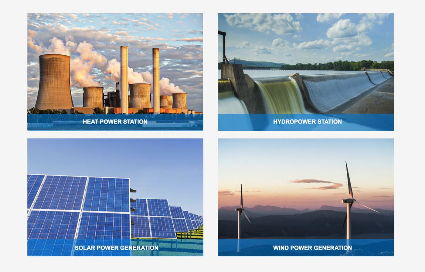
Part Ⅵ: Application
Part Ⅶ: Packaging and Transportation
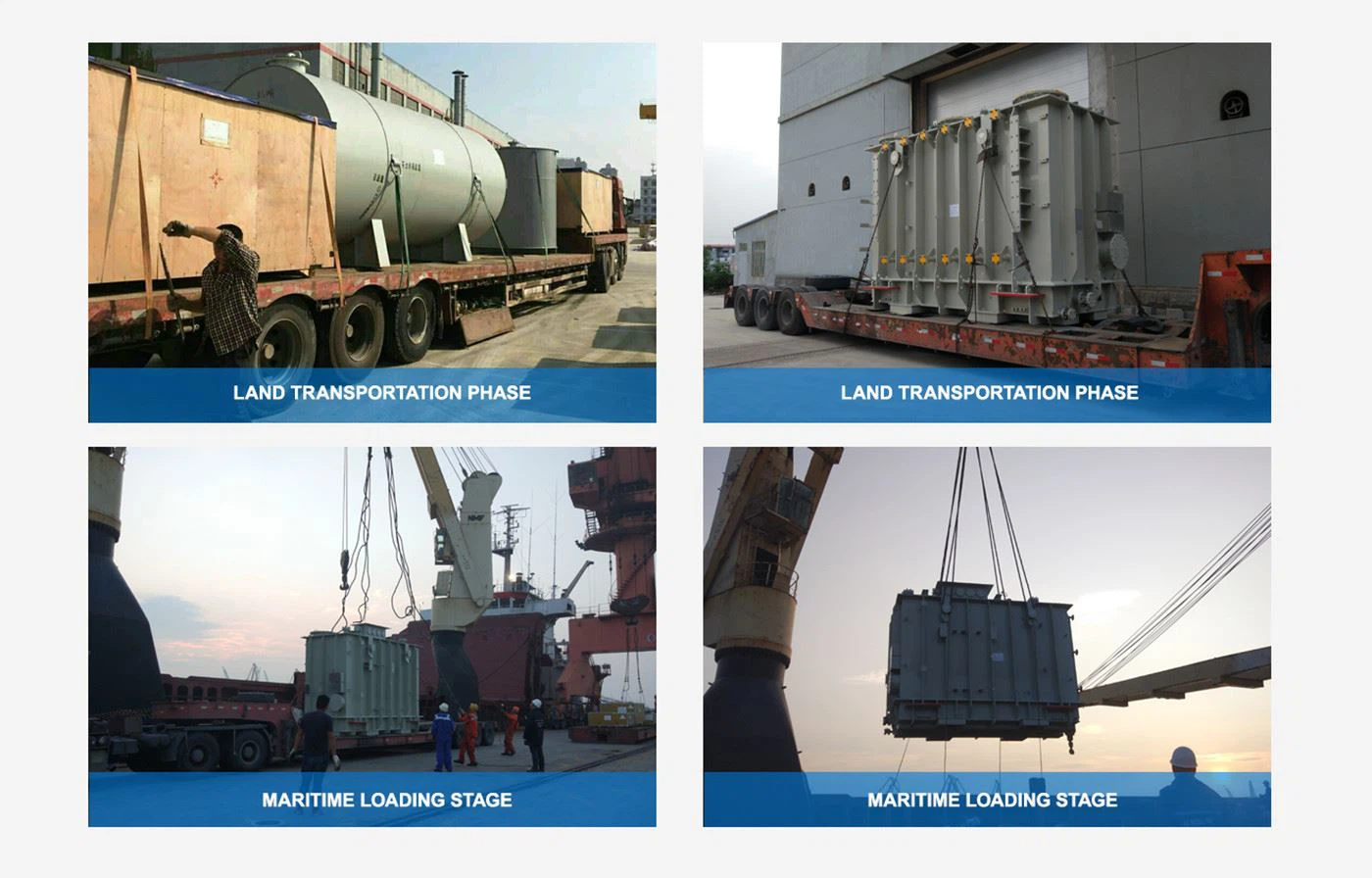
Before packing the transformer, make a packing plan, and carry out packing according to the design scheme and plan when packing. The packing list corresponds to the materials in the box one to one. Pack the box in two copies, one in the packing box and the other nailed outside the packing box. Important parts and spare parts are packed in wooden boxes, and the box numbers are set in order.
The transformer is transported in bare installation, and the fuel tank is emptied before transport. It is tied to a transport vehicle by a wire rope, and the transport speed does not exceed 15km/h.
The terminal is guaranteed to have large-scale transformer lifting equipment, and the lashing is firm after loading to ensure safe and reliable transportation.
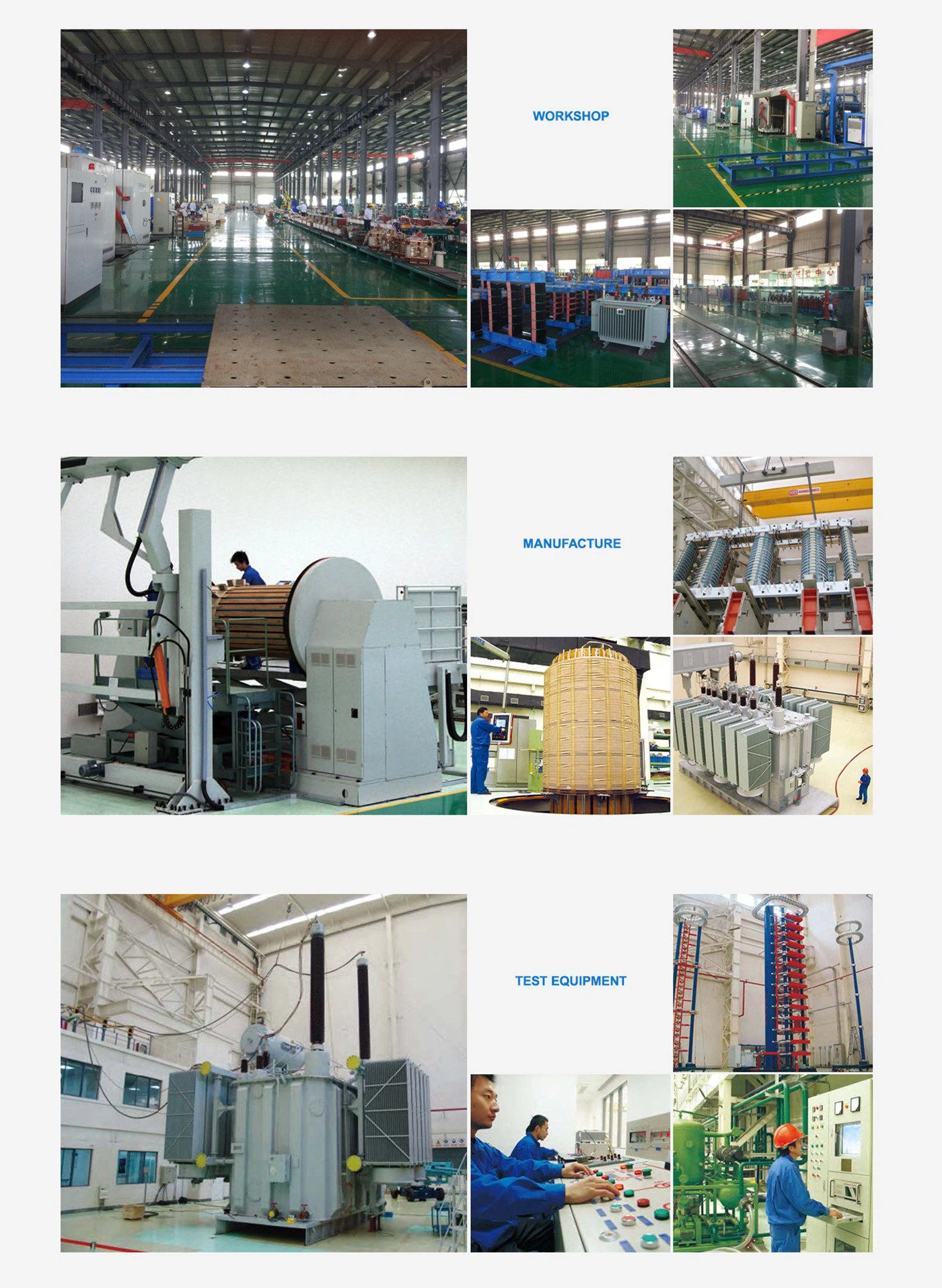
Part Ⅷ: Factory Tour
Part Ⅸ: Service Guarantee
1. To provide all technical information and drawings as per contract promptly. Everhydro is oblidged to invite client, if neccessory, to attend technical design review.
2. To carry out spot technical service as per client' s schedule, offer guideness for installation and commis- sioning according to technical information and drawings.
3. For relevant auxiliary equipment procured by customers. EverHydro will provide related technical information to meet requirement of equipment interface.
4. To execute stipulations in MOU or agreement signed by seller and buyer strictly.
5. To train staff from client for equipment installation commissioning, application, maintenance as stipulated in the contract.
6. To reinforce pre-sales, mid-sales, after-sales service to carry out "24-hour service", "service in advance", "overall process service", "lifelong service"in our manufacturing, installation, commissioning and maintance.
7. To meet spare parts requirements by customers at any time.
Part Ⅹ: FAQ
Q1: What is your MOQ?
A1: One set.
Q2: Is OEM/ODM available?
A2: Yes. All transformer can be customized by your requirements.
Q3: How long is your delivery time?
A3: It depends on your order quantity and generally it takes about 30~40days.
Q4: How long is the warranty?
A4: Within one year from sale date.
Hot Tags: resin insulated dry type transformers of 35kv level and below, China, suppliers, manufacturers, factory, price, made in China